Knowledge of residual stress, crystal orientation, and case depth prevents waste and premature failure when making parts for high-load or high-precision applications. These factors all play roles in strength, fatigue resistance, and wear resistance and can cause distortion that leads to dimensional errors. Appropriate QA procedures that integrate analysis into manufacturing prevent these problems, saving money and protecting the producer’s reputation.
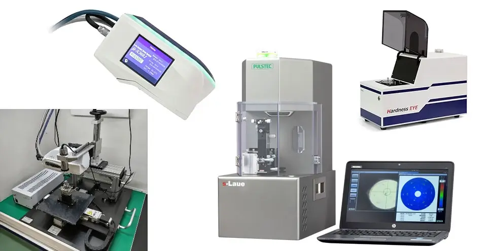
X-ray diffraction (XRD) is a non-destructive technique for performing residual stress analysis, testing case depth hardness, and gauging crystal quality. However, each of these tests requires a specialized piece of equipment. Pulstec manufactures four such XRD devices for industrial QA. These are:
- μ-X360J
- Hardness EYE
- m-Laue crystal orientation system
- s-Laue crystal orientation system
μ-X360J Stress Analyzer
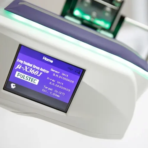
Pulstec’s μ-X360J portable XRD system uses a 2D detector to capture the full Debye-Scherrer ring or the diffraction pattern resulting from directing an X-ray beam into a measurement sample. The equipment is easy to set up and measures samples quickly (within 40 to 90 seconds, depending on what is being measured), using the lowest possible levels of X-ray energy.
The μ-X360J allows manufacturers to measure:
- Percentage of retained austenite
- Surface stress after shotpeening
- Stress distribution in stamped components
- Stress balance in precision shafts
Retained Austenite Verification
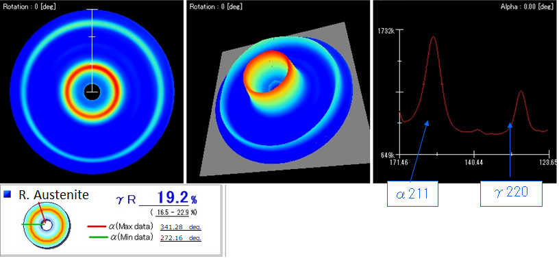
Steel parts often undergo heat treatment to raise hardness and toughness. The carbon content and temperatures used in manufacturing are key to transforming austenite into martensite to achieve the desired properties. Checking the amount of remaining austenite (retained austenite) is a way of verifying process results.
The μ-X360J measures retained austenite as a percentage by comparing diffraction peak profiles generated by different crystal structures. Austenite is face-centered cubic, while martensite is body-centered cubic, and these create different angles of diffraction when illuminated by X-ray.
Surface Stress Analysis (Shotpeening)
Shotpeening puts compressive stresses into the surface of a metal part. These compressive stresses counter the tensile stresses caused by machining and help increase fatigue resistance. However, achieving consistent results between parts is difficult because shotpeening is hard to regulate, and there is typically no information on the part’s initial stress levels.
The μ-X360J uses the cos-α technique to measure residual stress before and after processing to check the amount of shotpeening required and to verify that the target range of residual stress has been achieved.
Stress Distribution Evaluation (Stamped Components)
One of the challenges of hot stamping is that stress resulting from deformation can cause distortion that puts parts outside geometric limits.
Stress analysis by XRD, particularly when using the cos-α technique, is a fast and accurate means of quantifying stress distribution. This supports process and tooling development, reduces waste, and ensures consistency between parts and production runs.
Understanding Stress Balance (Precision Shafts)
Straightness and concentricity are critical in precision shafts, such as those used in aerospace, automotive, and medical devices, but residual stresses can throw these factors off.
Residual stresses are a direct result of the turning and grinding processes. These stresses cause distortion that may not show up until a lot of value has been added to the part.
With the μ-X360J, it’s possible to determine residual stress levels to optimize final machining operations, maximize precision, avoid expensive scrap and shipment delays, and ensure customers receive shafts that meet specifications and performance standards.
Hardness EYE

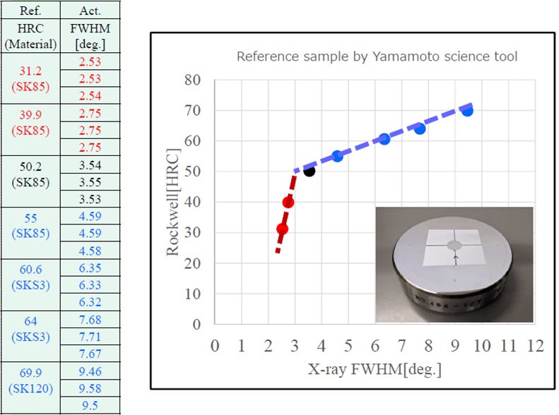
Steel parts like gears and shafts often undergo case hardening to increase wear resistance while preserving toughness and ductility. Case hardening should prolong part life, but durability depends on either effective or total case depth falling within the specified range.
Case hardness is typically verified through sectioning and micro-hardness testing. An alternative to this destructive method is XRD, as implemented in Pulstec’s Hardness EYE tester.
XRD yields Debye-Scherrer ring data with a distinctive peak. The Full Width Half Max (FWHM) of the peak has a strong correlation with hardness, making this a powerful, repeatable, and non-destructive method for evaluating and verifying case hardness.
Laue Crystal Orientation Systems
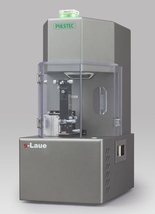
One emerging, non-destructive method for determining crystal orientation range and quality is the Laue diffraction method, which involves sending a beam of “white” X-rays into the sample and viewing the resulting diffraction pattern (Laue spots). Pulstec manufactures two systems that use the Laue method to verify crystal orientation range and quality: the s-Laue for smaller, in-lab measurements and the m-Laue for flexible, inline setups and on-site measurements of large parts, including turbines. Both devices can acquire Laue spots in less than 80 seconds.

Understanding crystal orientation range and quality in different materials is critical because it can impact strength and other directional properties. By understanding this directionality, it’s possible to orient the material as it passes through manufacturing processes to optimize the performance of finished parts.
A prime example is checking crystal orientation before cutting turbine blades, especially single-crystal or directionally solidified blades. Manufacturers can improve creep resistance, fatigue resistance, oxidation resistance, thermal performance, and mechanical strength by verifying crystal direction and aligning the cut to the ideal orientation.
Understanding crystal orientation in semiconductor wafer grinding is also important because the electrical, optical, and mechanical properties of semiconductor materials are anisotropic, meaning that they vary based on direction within the crystal lattice. Correct orientation will determine device performance, reduce circuit layout errors or defects in pattern transfer, prevent microcracking and chipping, reduce wafer yield, and optimize etch rates.
Likewise, using Pulstec’s Laue devices to verify crystallinity and orientation in crystal growth processes ensures uniform mobility and bandgap, minimizes defects, and prevents mismatched lattice strain and poor epitaxial quality.
Request a Demo or Sample Measurement Today
Manufacturers throughout the United States rely on Pulstec’s precision electronic equipment for research, on-site measurements, and in-situ measurements. Since our founding, we’ve been committed to helping our customers enhance their understanding of the materials they work with and optimize manufacturing processes.
Request a free demo or sample measurement today, and learn more about how Pulstec’s devices can help improve your company’s Quality Assurance processes.