Residual stress can accelerate fatigue cracking and lead to in-service failure, so to prevent this, structures like bridges, pressure vessels, pipelines, and railroad components are periodically examined.
Some residual stress measurement methods involve drilling holes or cutting into the parts being analyzed, but this is impractical for field structures subject to ongoing heavy loads. Instead, field measurements are performed using non-destructive analysis methods.
This article compares four widely used non-destructive residual stress analysis methods: magnetic flux leakage, ultrasound, acoustic emission (AE), and X-ray diffraction (XRD).
Magnetic Flux Leakage
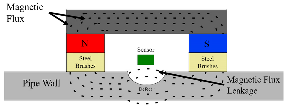
This method uses a transducer to generate magnetic fields in which the lines of flux run through a body rather than protrude from its surface. Defects in the metal divert the flux and move it through the surface (the leakage), which is then sensed and logged as a potential defect.
Main Advantages
- Typically doesn’t require surface treatment
- Can scan a large area quickly
- Finds material defects, such as small cracks
- Practical for field analysis
Main Limitations
- Only works on ferrous materials that can be magnetized
- Indicates areas of high stress, but does not provide stress measurement (calibration is needed for any degree of quantification)
- Material defects, such as cracks, can mask residual stress
- Not practical for complex geometries where flux may leak around bends, radii, and changes in thickness
- Previous magnetizations of the metal for analysis will influence the results
Common Applications
Magnetic flux is primarily used for identifying pitting, corrosion, and wall loss in steel structures, including storage tanks, pipelines, bridges, and railroad components.
Ultrasound/Ultrasonic
Ultrasonic inspection involves sending high-frequency sound waves into a solid body. Changes in density generate reflections that the transducer picks up.
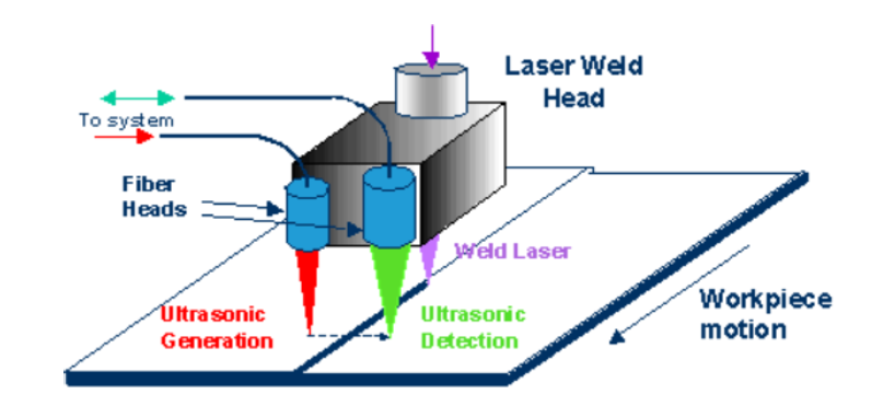
For residual stress analysis, this technique is modified to create longitudinal waves through the body parallel to the entry surface. The time-of-flight (ToF) of these waves over a known distance is measured, as their speed is affected by stress-induced changes in the material, known as the acoustoelastic effect. By calibrating against a stress-free version of the same material, it’s possible to calculate stress from its impact on ToF.
An emerging variant uses laser excitation. Research has shown the value of this approach, and commercial products may become available in the future.
Main Advantages
- Works on ferrous and non-ferrous metals and many nonmetals
- Yields quantified stress measurements
- Portable for field analysis
- Can measure stress in different directions
Main Limitations
- Microstructure variation can result in incorrect stress values
- Affected by changes in temperature
- Produces an average stress value
- Requires calibration on identical (but unstressed) material
- Sensitivity to surface stress is lower
- Part geometry must provide enough space for the transducer to be positioned appropriately
Common Applications
Being portable, ultrasound is used in several applications requiring field or in-situ measurements. It’s often used to measure residual stress in welded structures such as pipelines and pressure vessels, as well as in rails and wheels. It also works well for measuring interior stress levels in thick metal sections.
Acoustic Emission
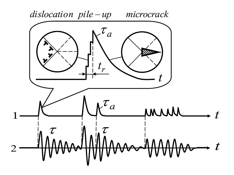
Acoustic Emission, or AE, is performed in two modes: transient and continuous. In transient AE, signals above a threshold are captured, whereas continuous AE captures all data generated. Both methods involve loading or deforming a part and listening for responses from cracking or microstructure.
Main Advantages
- Portable, suitable for field analysis
Main Limitations
- Does not produce stress values, only indications
- Requires that the object under test be stressed beyond the previous maximum level experienced
- Reduced sensitivity in noisy service environments
- Slower than alternative methods
- Results are affected by the age of the materials
Common Applications
AE is used during proof loading or pressure testing when loads are first applied. It is useful for detecting small cracks in structures like pipes and pressure vessels, corrosion pitting, and hydrogen-induced defects.
XRD
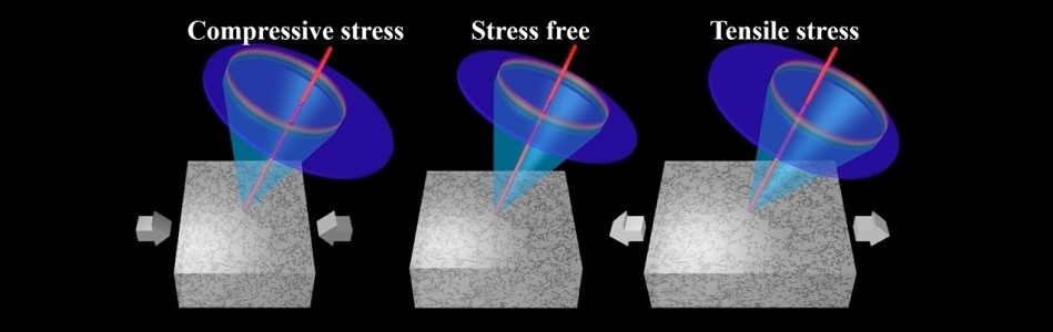
XRD equipment uses a zero- or one-dimensional sensor, or a high-sensitivity 2D sensor, depending on the method (e.g., cosα versus sin2𝜓) to direct an X-ray beam onto the surface of a crystalline material and observe how the structure scatters it. The lattice spacing (“d-spacing”) is deduced from these measurements. Once the d-spacing is known, comparing a nominal unstressed sample with a stressed sample allows the determination of the stresses present.
Main Advantages
- Measures the actual strain produced by the stress
- Equipment is compact and portable, ideal for on-site work
- With the cosα method, measurements are made, and results are produced very quickly
- Measures residual stress at the surface (the priority region in terms of fatigue crack initiation)
Main Limitations
- The surface may need some preparation to remove dirt, rust, paint, and debris
- Only works on crystalline materials
- If not using the cosα method, the analysis equipment needs careful alignment
- Some shielding is required to protect against radiation
Common Applications
XRD is used in many residual stress field measurement applications, ranging from bridge inspection and maintenance to pipelines, pressure vessels, and cranes. It’s also used after post-weld heat treatment and shot-peening for validation of stress reduction. Another large application area is inspection of railway tracks, wheels, and axles, to prevent in-service failures.
Learn More About Pulstec’s μ-X360J
Founded in 1969, Pulstec helps manufacturers, research and development departments, and engineers quickly and accurately test for residual stress. We’ve developed several innovative equipment lines, including our μ-X360J XRD analyzer, which can be used for in-lab or field measurements. Our analyzer uses a 2D sensor for more precise measurement and provides results on ferritic steel samples within 40 seconds.
Contact us today to get started with a free virtual demo.