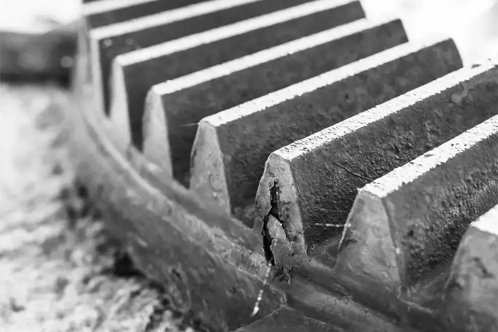
Residual stress, particularly in gear teeth, plays a large part in determining a gear’s fatigue life, efficiency, and noise level. Additionally, heat treatment and processes like shot peening, which are sometimes required in gear manufacturing, change residual stress levels, so it’s important for engineers to understand how these levels change throughout the manufacturing process.
Despite the importance of measuring residual stress, the process of measuring gears isn’t straightforward, and many materials researchers have to resort to destructive techniques to adequately measure the gear.
In this blog, we’ll further discuss the causes and impact of residual stress on gears, the challenges of modern measurement methods, and how Pulstec’s XRD technology can resolve some of these challenges.
Table of Contents
Causes & Impact of Residual Stress on Gears
Causes
Residual stress results from distortion of the crystal lattice. Reducing the atomic spacing causes compressive stress, while increasing it results in tensile stress. Casting, forging, machining, and heat treatment are all processes that contribute to residual stress.
Heat treatment is an especially significant cause of gear residual stress. Heat treatment is important to raise strength and toughness while imparting a hard, wear-resistant surface. However, processes like carburizing and nitriding pack more atoms into the surface region, which increases compressive residual stress. Furthermore, induction hardening, quenching, and other heat treatment processes alter the proportion of retained austenite, which also impacts fatigue life.
Impact
Over time, cyclic loading of gear teeth leads to fatigue and failure, and to further compound this problem, power densities are getting higher as applications like wind turbines and electric vehicles (EVs) need to push more torque through smaller transmissions. Stress levels are highest at gear teeth roots, which is where fatigue cracking appears first. Fatigue is countered by raising levels of compressive stress at the surface, which, thanks to the equilibrium principle, means internal tensile stresses must be higher too.
Machining inevitably disturbs this equilibrium, resulting in distortion of teeth geometry. While very small, this machining is enough to reduce efficiency and increase wear. It also raises noise levels, which is a particular concern in EVs.
Current Challenges With Measuring Residual Stresses
There are two primary methods of measuring residual stress in gears: 1) contour method and 2) X-ray diffraction (XRD). The first of these looks at internal or bulk stresses, while the latter is used to measure surface residual stress. For gear teeth, surface residual stress is of most interest because this relates to fatigue life and distortion.
Let’s take a look at both methods and their challenges.
Contour Method
The Contour Method is destructive, as it requires sectioning the gear. The sectioning/cutting is typically done with wire electric discharge machining (EDM) because it doesn’t induce any additional stress.
After the gear is cut, the two halves of the gear deform slightly because the residual stress is redistributed. The deformation of the cut surfaces is then measured using laser scanning, contact profilometry, or another high-res technique. Once measurements are taken, the principles of elasticity and the finite element analysis model are applied to calculate the original stress distribution before the gear was cut.
Overall, the process is slow, expensive, and doesn’t yield information about surface residual stress, but it can help look at internal or bulk stresses.
Beyond its destructive nature and the fact that this method can only be used to measure bulk stresses, additional limitations of this method include:
- Surface Roughness: Irregularities on the cut surface (roughness, waviness, etc.) can introduce noise.
- Misalignment: Misaligning the cut sections during scanning will lead to measurement inaccuracies.
- Complex Analysis: The stress calculation relies on high-fidelity finite element analysis and careful interpretation. Errors in modeling assumptions or boundary conditions will skew results.
- Limited Stress Resolution: The Contour Method only measures residual stress on the cut plane, so any stress outside of this plane won’t be captured, further limiting the understanding of how residual stress is distributed.
- Geometry: Gears have a complex geometry, making it difficult to cut accurately and measure with sufficient resolution.
- Material: Certain materials may deform excessively or fracture during cutting.
XRD
X-ray diffraction involves pointing X-rays at a polycrystalline material and analyzing the return pattern.
Besides its focus on the surface, a major advantage of XRD is that it’s non-destructive. However, gear tooth geometry poses a major problem for most XRD measurement systems. In XRD, an X-ray beam is sent to the surface of the part being analyzed. Diffraction scatters the beam, which is captured by a detector and measured. The shape of most gears, notably spur gears, restricts the available viewing angles. This is usually addressed by cutting away one tooth to allow measurement of the one adjacent.
Additional limitations of the standard XRD technique are:
- Limited Depth of Penetration: Only the top few microns are examined, making it impractical for subsurface stress analysis. Electrolytic polishing can increase the effective depth through material removal, but that will induce some damage to the gear, making it unsaleable.
- Lack of Spatial Resolution or Sensitivity: Residual stress can change over the flank of a gear tooth, which most systems cannot pick up.
- Anisotropic Behavior: Anisotropic behavior and microstructural gradients within the gear (after heat treatments and surface hardening processes) reduce measurement accuracy.
- Finish: Surface coatings will reduce measurement accuracy, and rougher surfaces also increase scattering, so polishing is often needed for repeatable measurements.
- In-Situ: A further challenge is the lack of techniques for in-situ measurements, making it difficult to monitor residual stress in real time during machining and heat treatment.
Pulstec’s Solutions
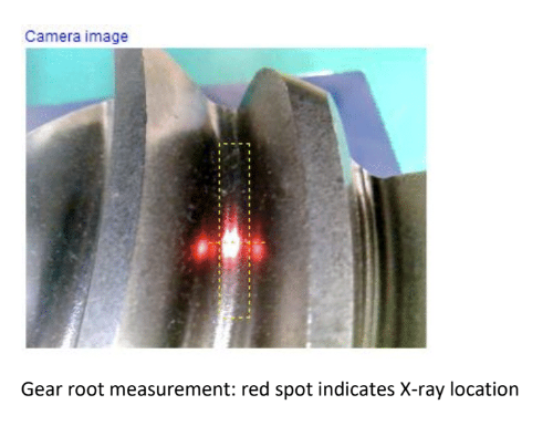
Pulstec has worked tirelessly to find a solution for accurate gear measurement and has found it with the μ-X360J, a lightweight, portable X-ray residual stress analyzer that can non-destructively measure residual stress in as little as 40 seconds. This analyzer has several features designed to address the challenges of conventional XRD technologies:
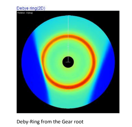
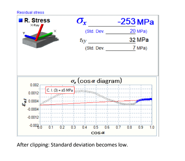
- Two-Dimensional Detector: The μ-X360J uses the cosα technique for imaging the Debye-Scherrer ring. The two-dimensional detector allows researchers to capture the entire Debye-Scherrer ring, which was not possible with the sin2 ψ method, which many XRD technologies still use.
- Optional Tri-Axial Stage: Pulstec offers a wide range of optional accessories, including the tri-axial stage, which makes controlled oscillation of the sensor unit possible. Controlled oscillation makes it easier to accurately measure complex geometries and curved surfaces.
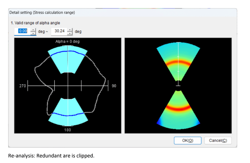
- Reanalysis Function: The software for the μ-X360J features a “reanalysis” function, which provides the option to repeat the measurement on a different area of the target. The analyzer software allows tracking of multiple data points, which can be included when analyzing the results. To use this function, the operator readjusts the sample and angle, adjusts the measurement position in the software, conducts an operational test for errors, and then starts the measurement.
- Optional Electrochemical Polisher: If subsurface analysis or depth stress distribution profiles are required, an available electrochemical polisher allows localized, controlled electrolytic material removal.
- In-Situ Capability: Pulstec’s equipment has been extensively used in research studies, like this one. This study used the μ-X360J to perform in-situ measurements during fatigue tests and found that the analyzer enabled real-time monitoring of residual stress relaxation through the fatigue testing process, further helping understand how residual stresses evolved under cyclic loading conditions. The μ-X360J’s in-situ capability primarily stems from its compact and portable design, high-speed measurement capabilities, non-destructive method, and its ability to be integrated with most fatigue testing setups.
In addition to the μ-X360J, Pulstec offers a robotic residual stress mapping system with stress mapping capabilities. This system features a robotic arm with a 3D scanner. Once programmed, the robotic arm can position the sensor in the orientation needed to make measurements at multiple locations, and its 3D scanner uses the triangulation method, which increases accuracy when analyzing curved surfaces and parts with complex geometries, such as gears.
Learn More About Our Solutions Today
Founded over 50 years ago, Pulstec is an electronic equipment manufacturer known for engineering innovative equipment like our μ-X360J and robotic residual stress mapping system. Contact us today to learn more about our gear measurement solutions or to request a free product demo.

