
The individual grain structure within crystalline materials, such as metal alloys, influences mechanical properties. In aerospace, stray grains or deviations in crystal orientation within single-crystal components, such as turbine blades, can increase the risk of catastrophic in-service failure.
This influence is why crystal orientation verification is so critical in manufacturing. Diffraction is one of the most heavily researched and trusted methods for this application, with X-ray diffraction (XRD), including Back Reflection Laue and Transmission Laue, and Electron Backscatter Diffraction (EBSD), as primary techniques.
Table of Contents
Laue Method

The Laue Method, founded by Max von Laue in 1912, can be described by Bragg’s Law to establish the initial relationship based on how X-rays interact with a crystalline sample.
In the Back Reflection technique, broad-spectrum (white) X-rays are directed on a crystalline sample, and as the X-rays reflect back, create a diffraction pattern. Comparatively, the Transmission technique involves directing X-rays through crystalline materials. The first method is primarily used on thicker samples, while the second requires thin samples.
Benefits
- Non-destructive
- Doesn’t require surface preparation/surface damage and is less sensitive to surface damage and condition
- Can verify crystal orientation on larger parts with awkward geometries, such as turbine blades
- Fast process, depending on the equipment
Limitations
- Back reflection is a single-crystal technique or coarse grain technique, although micro- and nano-Laue methods exist to analyze fine-grained polycrystals
- Can’t measure hydrostatic strain without an added energy scan
- Mapping can be challenging
- Possible to obtain plane directions, but not absolute d-spacings
- Poor spatial resolution in the lab
- Overlapping harmonic reflections are possible
- Smeared spots can form from deformed crystals
Known Use Cases
- Orienting single crystals before cutting or growth
- Detecting stray grains or misoriented regions in turbine blades
- Aligning crystals for neutron scattering, magnetic, and transport measurements
- Assessing crystal quality
Electron Backscatter Diffraction
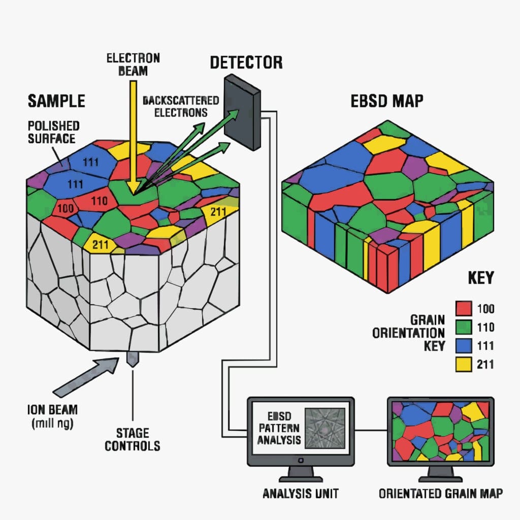
Electron Backscatter Diffraction is a well-known method in the metallurgy industry. It doesn’t rely on X-ray irradiation. Rather, the process works by targeting a monochromatic electron beam at a tilted sample. The incident electron scatter inside the sample and create a diffuse point source. The electrons that meet Bragg conditions for each plane family are channeled into pairs of cones, each of which intersect a phosphor screen or direct electron detector as Kikuchi bands. Each band is a projection of a lattice plane, and the software used in the process indexes each pattern in milliseconds and builds an orientation map point by point.
Benefits
- Pattern indexing is fast
- Can be integrated with SEM imaging, EDS, in-situ heating or straining stages, and FIB serial sectioning for 3D processes
- Provides fine spatial resolution
- Can be automated
Limitations
- Surface damage, whether polishing deformations, oxide, or other contamination ruins pattern quality
- Requires electropolishing or broad ion beam milling
- Size limitations, as each sample must fit within the chamber
- Provides only surface measurements; bulk behavior has to be inferred
- Some structures and phases, including ferrite and low-carbon martensite, are hard to distinguish
- Mapping is possible, but can take hours, and drift is a risk
Known Use Cases
- Analyzing the texture of rolled, recrystallized, and annealed metals
- Measuring grain size
- Grain boundary engineering
- Retained austenite and phase analysis
- Weld and heat-affected-zone characteristics
- Crystallographic preferred orientation in rocks
- Elastic strain and GND density mapping
What Is the Better Option?
Laue and EBSD both use Bragg’s Law as guiding principles, are used to analyze crystalline materials, and have been extensively researched. In many ways, these processes are actually complementary. Laue answers “what is the orientation and quality of a large crystal without touching it” while EBSD is used to figure out how the orientations, phases, and boundaries are distributed across a microstructure at sub-micron scale.
The better process lies in the application objectives. Is the goal to orient a single crystal, or examine deformation or recrystallization in a polished section of a sample?
Request a Project Analysis
Founded in 1969, Pulstec engineers revolutionary X-ray diffraction equipment, including the μ-X360J residual stress analyzer and our s-Laue and m-Laue single crystal orientation systems, designed for lab and manufacturing applications.
Visit our blog for more resources, or contact us today to request a project analysis, free product demo, and three complimentary measurements.