
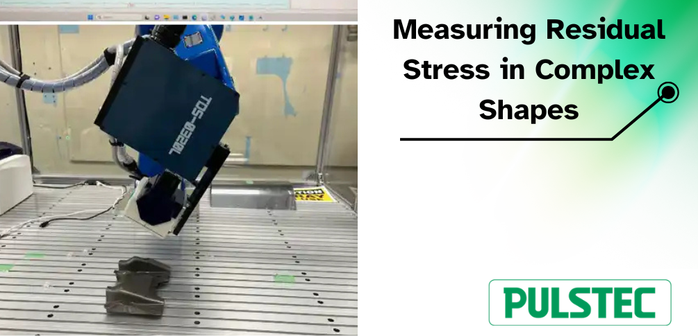
When surface residual stress measurements must be nondestructive to preserve the integrity of the sample or product, X-ray diffraction (XRD) is the preferred solution. However, components with complex geometries or shiny surfaces introduce challenges that flat, matte samples don’t.
Convex and concave surfaces and deep pockets pose particular challenges, and the problems grow as radii shrink because the X-ray beam is distorted from its normal elliptical contact form, can be defocused, and may have its diffract signal partially blocked.
A shiny finish has no effect on how X-rays will diffract, but it can pose challenges for the optical systems used to position the instrument. Additionally, surface preparation performed via mechanical polishing can alter surface residual stress levels through plastic deformation, heating, compression, and material removal, which leads to inaccurate or erroneous data.
Despite these challenges, measuring residual stress on components with complex geometries isn’t impossible and can be achieved by following these best practices:
Table of Contents
Use the cosα Method
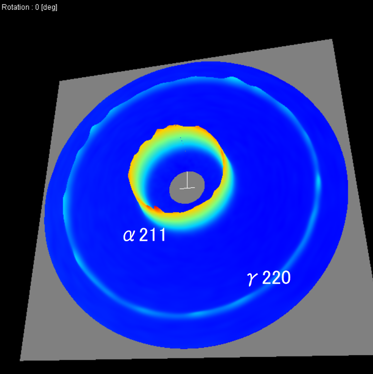
Unlike the sin²ψ method, which requires multiple acquisitions at differing angles of incidence, the cosα method uses a 2D detector to capture an image of the full Debye-Scherrer diffraction ring in a single setup.
Using the cosα to measure residual stress on complex shapes simplifies positioning requirements. It can be used with a small diameter X-ray spot and placed in a way that maximizes signal integrity while avoiding distortion or any blocking of the diffracted beam.
Oscillate Samples
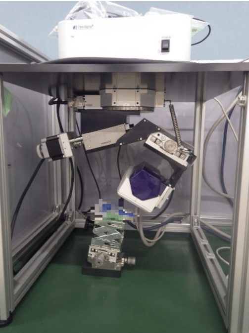
Oscillation, which can be planar or rocking, scans the X-ray beam over a larger area or more grains. Often used with bigger samples, oscillation increases the sampled area, which averages the residual stress values obtained and increases measurement repeatability. It also reduces the negative influence of larger metal grains that can give misleading numbers.
Set Up Angles & Distances With the Triangulation Method
Even when using cosα rather than sin²ψ, it’s important to set up incidence and detection angles correctly, and the sample has to sit at the right standoff distance. The cosα calculation assumes a known sample-to-detector distance when it converts the Debye-Scherrer ring into stress values.
This known distance is straightforward on flat surfaces, but on curved surfaces, especially surfaces like gear teeth where radii vary, the distance is much harder to judge, and that difficulty grows with a small-diameter beam.
Triangulation is the optical solution. In the Triangulation Method, a laser is projected onto the surface at a known angle while a sensor views the illuminated point from a fixed offset. Because the geometry between the laser, sensor, and surface is fixed, any change in standoff shifts where the point lands on the sensor, and that shift resolves to an exact distance rather than an estimate.
While Triangulation works well for curved surfaces, there is still an additional challenge with shiny surfaces. The Triangulation Method depends on the sensor catching light scattered back from the surface. A shiny finish reflects the laser away in a single direction instead of scattering it, leading to unreliable readings. A high-sensitivity triangulation scanner can recover the weak diffuse signal and maintain reading accuracy.
Maintain Stability With a Robotic Arm
When measuring residual stress in complex shapes, any movement of the sample relative to the XRD unit can lead to significant variation in results. In such cases, an articulated arm can be useful for holding the sample in a stable position.
Choose the Right Collimator Size
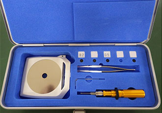
The X-ray beam should be sized appropriately for the surface being measured. While diameters up to 5 mm are often preferred for their averaging ability, on complex forms this can lead to diffraction from areas outside the region of interest.
The collimator sets the size of the X-ray beam, and should be selected to ensure data is only gathered from the target area and not from surrounding material. Note that a smaller diameter beam also improves spatial resolution of the results when scanning over an area.
Use an Electrochemical Polisher for Depth Measurements
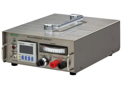
XRD generates diffraction from the top 5–30 μm of the surface, although the exact penetration varies based on the X-ray tube material, incident angle, and material density. Getting data from deeper into the material requires removing the uppermost layer. This material removal is best done via electropolishing, which removes material without altering surface stress or creating any heat.
Electropolishing is also beneficial when the surface has been polished. Removing the uppermost layers exposes material that will provide more meaningful residual stress measurements.
Keep the Peak Fitting Consistent
Peak fitting is used to determine the highest points of the Debye-Scherrer ring, and is a core part of XRD. This is especially true when using the cosα method to develop a full circle. Poor or inconsistent peak fitting results in incorrect or misleading results.
Accurate and consistent fitting requires sophisticated software that analyzes the data generated by the system. When comparing XRD systems, always include the software capabilities as part of the review.
Get Help From Pulstec
Pulstec is a Japanese developer and manufacturer of XRD equipment for applications ranging from residual stress and retained austenite measurement to single crystal orientation.
Our μ-X360J XRD system provides fast and reliable residual stress measurements within 40 seconds, and can be safely used both in the lab and in the field. The μ-X360J can be outfitted with optional features or purchased with additional accessories, including a robotic arm with tri-axial oscillation capabilities and an electrochemical polisher for depth profile measurements.
We also manufacture a residual stress mapping system that supports 1-axis, 3-axis, or planar slide oscillations and features a high-sensitivity 3D scanner that uses the Triangulation Method to produce highly accurate data, even on shiny and lustrous objects.
Pulstec provides free virtual demonstrations. If you’re interested in learning how the μ-X360J can help you measure complex or shiny samples, contact us today. We offer up to three complimentary samples.