
Gas turbine blades, typically made from nickel-based superalloys, are sometimes produced through single crystal casting to improve strength and corrosion resistance. Single crystal casting eliminates grain boundaries that impede dislocation motion, preventing premature failure and allowing engines to run hotter and more efficiently.
However, these alloys are anisotropic in single crystal form, so mechanical properties vary with crystal orientation. To address this, casting processes are designed so the crystal structure is oriented to maximize performance in the highest load direction. Casting as a manufacturing process is also subject to many variables, and crystal orientation can vary within a blade and between blades.
It’s critical to verify orientation during the manufacturing process to identify the following characteristics:
Casting Defects
Verifying crystal orientation at various locations through a blade can reveal internal defects that occurred during casting and solidification. Stray grains and uncontrolled or incorrect dendrite growth are the main examples. As these could lead to in-service failure, detection is essential so defective products can be withdrawn and the casting process modified as needed.
Crystal orientation can also change gradually along the blade length, altering mechanical properties and increasing the risk of failure.
Stiffness & Vibration
In anisotropic nickel-based superalloys, the elastic modulus (which determines stiffness) varies by direction. This is an issue in turbine blades, as changing gas flows and other forces inside the engine can result in vibration.
Blade stiffness is optimized during design to avoid resonance problems, but changes in crystal orientation can also alter vibration response. Checking orientation ensures that any blades with stiffness outside design limits are identified before installation.
Creep Resistance
High working temperatures make creep a major concern during turbine blade design. Nickel-based superalloys are formulated for high-temperature strength, and the single-crystal structure increases creep resistance. However, peak resistance depends on correct crystal orientation. Additionally, any stray grains that form during solidification will cause areas of local weakness.
The possible consequences of creep occurring in service are severe, so crystal orientation verification should be an important part of turbine blade quality control.
Fatigue Resistance
In conventional, multi-crystal alloys, repeated cyclic loads produce stresses within individual grains, and grain boundaries can impede and redirect dislocation motion. Repeated cyclic loading can cause localized plastic deformation along crystallographic slip planes, forming slip bands that may initiate fatigue cracks.
In a single-crystal alloy, the absence of grain boundaries eliminates these barriers to dislocation motion, but cyclic loading can still produce localized plastic deformation and slip. The formation and extent of this slip depend strongly on crystal orientation because it determines how applied stresses are transferred into the material’s crystallographic slip systems.
Accordingly, single-crystal turbine blades are cast with a crystallographic orientation that’s selected to limit unfavorable slip under the main cyclic loading conditions. Maintaining the desired orientation helps minimize localized slip, reducing the potential for fatigue cracking.
Verification Challenges
Crystal orientation can be readily determined through the Laue method of XRD, which involves directing an X-ray beam into the sample and imaging the back reflection to determine the angles needed to achieve symmetry. With the right equipment, this can be done quickly, but there are some challenges:
- Surface conditions from machining, grinding, and other post-manufacturing processes can create scatter and noise in the image.
- Turbine blades have geometry that can be difficult to capture under the X-ray beam and are often relatively large and require multiple acquisitions.
- Inline methods are often difficult to implement because of the large footprint of the equipment needed.
How Pulstec Helps Manufacturers Verify Orientation
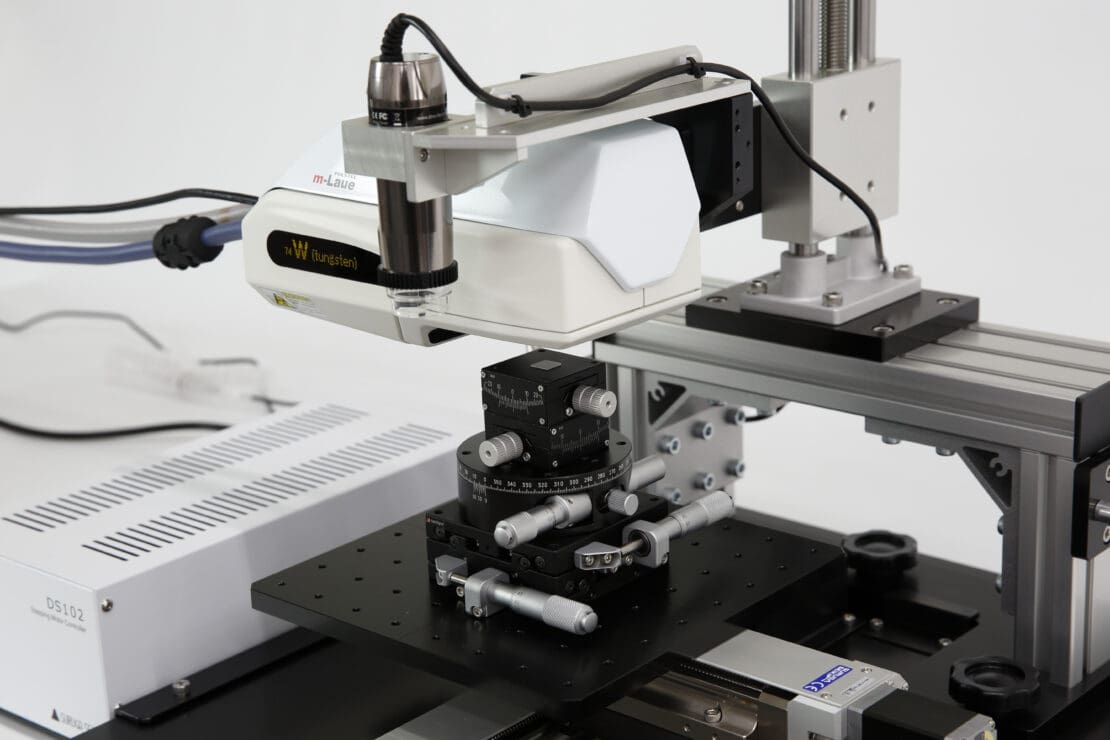
Pulstec manufactures two single crystal orientation verification systems: the s-Laue and m-Laue, both of which use the back reflection Laue method.
The s-Laue is engineered for in-lab use to measure principal plane orientation, check and adjust cutting orientation, evaluate crystallinity, and analyze processing-related crystal growth. The m-Laue is our flexible version, designed for integration directly into manufacturing processes for on-site crystal orientation measurement of larger parts.
Pulstec’s goal when developing both the s-Laue and m-Laue was reliability, speed, and ease of use.
Both models rely on X-ray diffraction, which is a no-contact, non-destructive method ideal for on-site quality inspections. The m-Laue allows vertical irradiation to improve the resolution of Laue spots, even when surface conditions are rough.
Unlike other conventional, non-destructive techniques, including EBSD, ultrasonic, and EMAT equipment, the m-Laue requires minimal training, beyond learning how to set the sample. It’s also compact and lightweight for easy installation, and it features an integrated mounting bracket customized to the machinery or equipment it’s installed on.
Once integrated into your quality control process, the m-Laue can acquire Laue spots in as little as 80 seconds, reducing the time and labor needed when verifying crystal orientation on larger turbine blades.
Request a Free Demo
Pulstec is a leading manufacturer of XRD equipment for industrial, laboratory, and field inspection and analysis, including the s-Laue, m-Laue, and our μ-X360J residual stress analyzer.
If you’re interested in learning how the m-Laue can improve your inline quality control process, contact us today to request a free demo and three complimentary measurements.